Developerbox Getting Started

This page is no longer the right place for Developerbox documentation. Please see:
- Front page
- ERP and Third Party operating systems
- Known problems
- Contribution guide (how to change the Developerbox documentation)
If you have any support questions related to your Developerbox please use the community forum.
This wiki can be edited but is only intended for content that is not suitable for inclusions in the main documentation (such as hacks for pre-production boards).
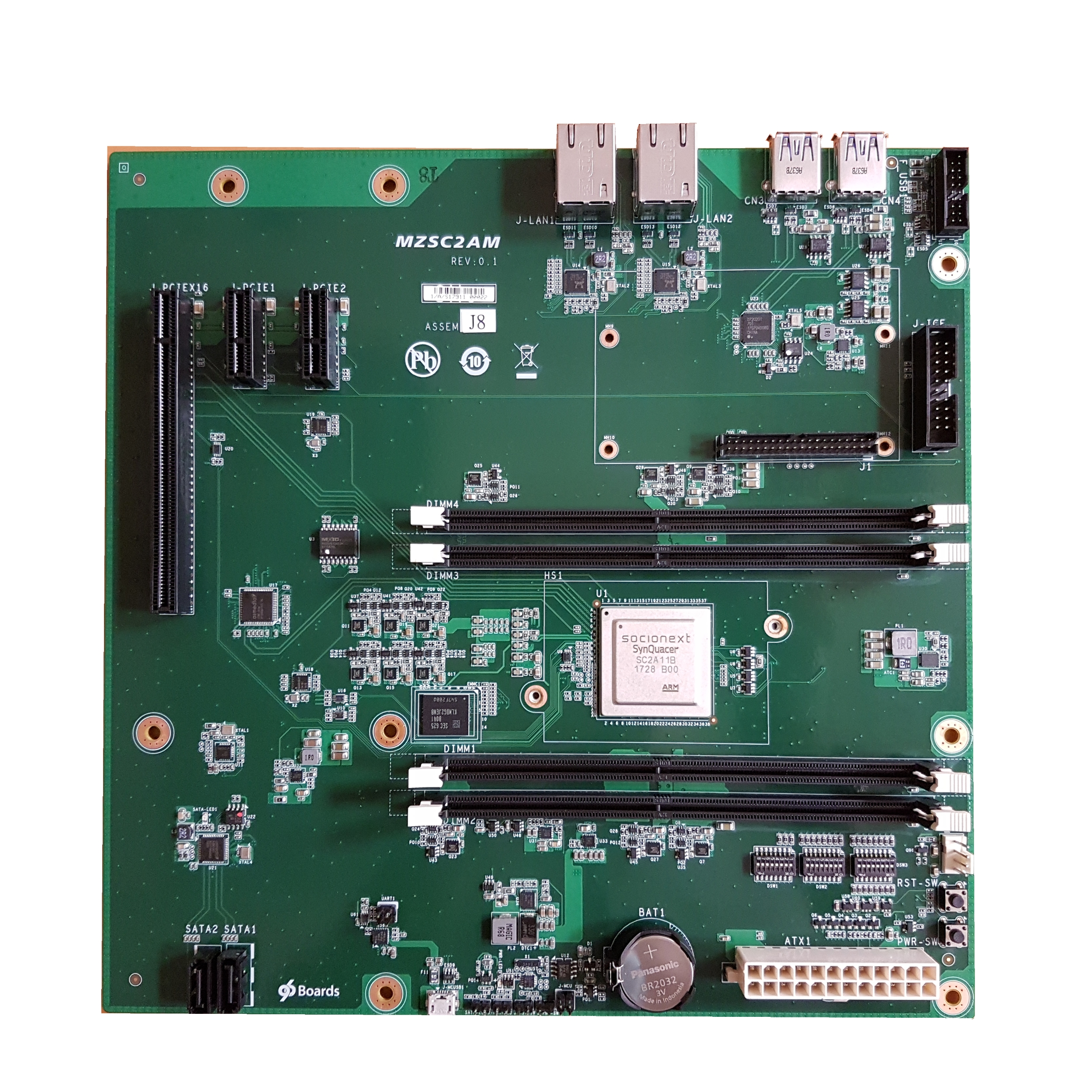
The main documentation does not describe the quirks of the pre-production boards. If you have a pre-production board additional information can be found here. If you do not know that you have a pre-production board then you almost certainly do not and you do not need to read this section!
The main system UART (used for OS console) is available via a micro-USB connector. On pre-production boards this connector is located on the back edge next to the front panenl pin header.
The CM3 SCP UART (used for low-level firmware upgrade) is availabled on the 96Boards low-speed connector: pins 1 (GND), 5 (TX) nd 7 (RX). Unfortunately on pre-production motherboards access is difficult because the LS connector has the wrong gender. Possible workarounds include:
- Use a 2x22 2mm female-to-female ribbon cable as a converter. There are two caveats here: 1) for most cables the sides of the socket on the motherboard must be physically snapped off to provide clearance to attach the cable and, 2) most ribbon cable have connectors on same side of the ribbon meaning they swap odd/even rows making it unsafe to attach mezzanine boards to all 40 pins, however the 96Boards-uart mezzanine can still be used but it must be offset so that only one row of pins is connected to the ribbon cable. There are four possible ways to attach a mezzanine like this (and at least one will likely do physical damage) to review the 96Boards GPIO Pinout carefully.
- Use 2mm female jumper cables to bring out just the UART signals from the LS connector.
- De-solder the male connector and replace with male 2x20 2mm header.
The rear USB3 sockets have D+/D- swapped preventing the sockets from working. This can be workarounded around with custom cabling (either by modding a broken out USB cable or by switching the D+/D- lines of a hub with a wired "uplink").
The reset switch (and associated pin header) is connected to an advisory reset line rather than the power-on reset, making it unreliable. The power-on reset signal is available on pin 4 of the 96Boards low-speed connector. If you have a chassis reset switch it is recommended to use jumper wires to connect the switch across pin 2 (GND) and pin 4 (PWR_BTN_N) of the LS connector.
As shipped the default DIP switch positions are:
- DSW1: All off
- DSW2: On (3, 4, 5, 6), Off (1, 2, 7, 8)
- DSW3: All off
Before reporting any problems with Developerbox please ensure that they have not been reported already (open issues) and that the problems described are specific to Developerbox.
Bugs can be reported at: bugs.linaro.org.